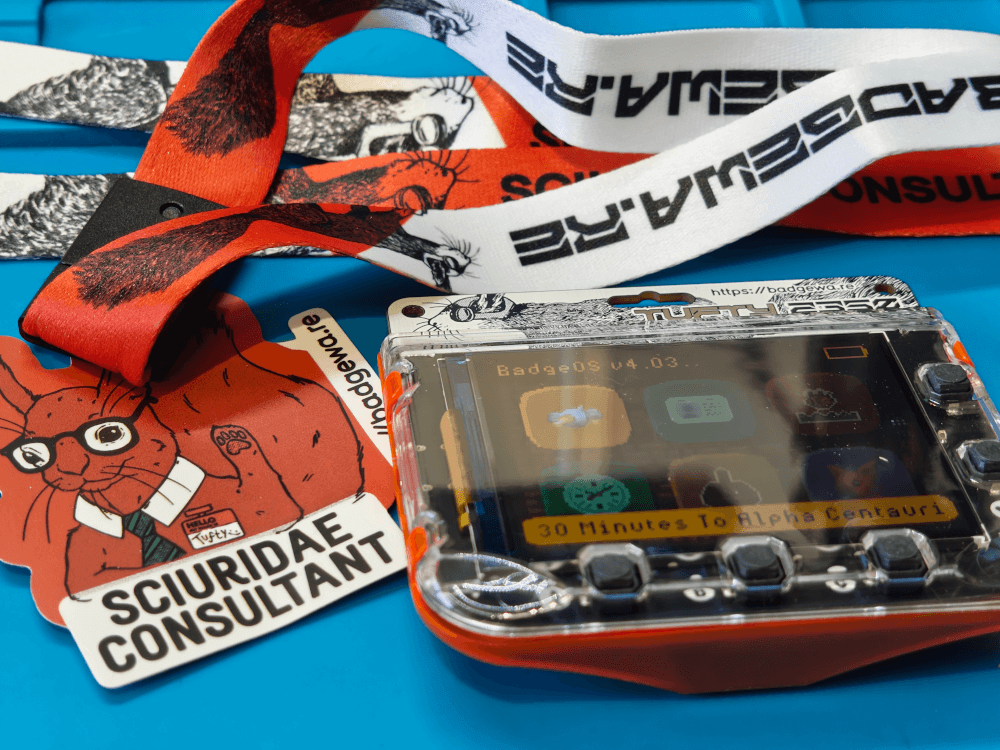
The Tufty2350 LCD badge is a 2.8 inch screen with a rechargeable battery in a sturdy case. It comes with a lanyard so you can hang it around your neck and the case is shaped so that it also doubles as a desktop stand. I bought the Tufty2350 LCD badge during the Pi Day sale a few months ago, but I've not really done much with it.
That was until a few weeks ago. I went to LocalGov Drupal Camp 2026 in Sheffield recently and decided to use it as a badge for the conference. I spent a few evenings before the event writing come MicroPython code to create a badge application that I used at the event. I was impressed with the badge itself, and it was certainly a topic of conversation from a few people over the event.
I also added a bit of extra functionality to the badge where users could scan a QR code that would take them to a form on this site, where they could enter a short message. That message would then appear on the badge within a few seconds.
I then wore the badge to the recent North West Audio show in Cheshire, where a few people commented on the badge.
In this article I'll look at the Tufty2350 LCD badge, some features about the badge, and then how to create a custom badge application.
Out Of The Box
The badge comes in a decent cardboard box that protects the badge well and contains the badge, a sticker, and a lanyard. The badge comes fully assembled and works right out of the box (although you may need to give it some power if the battery is flat).
The badge can be easily opened by unclipping a couple of plastic clips, revealing the high quality PCB and battery inside.
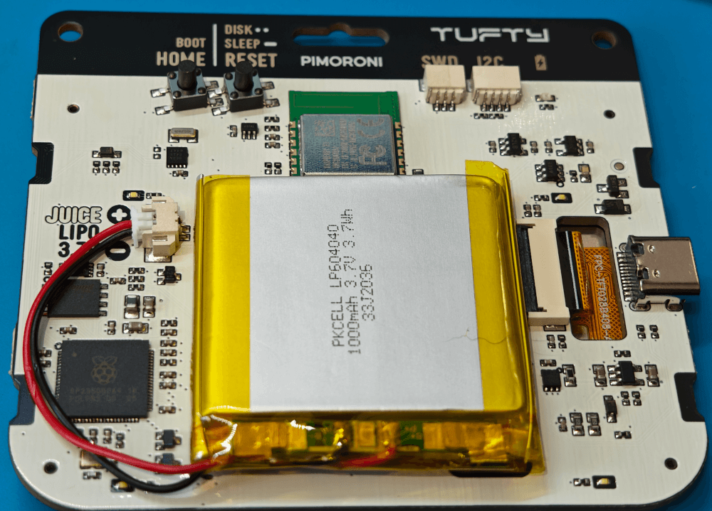
In fact, Pimoroni also sell a number of different badge cases in different colours so you are encouraged to open it up to swap the case and have a look at the internals.
Specifications
Here are the specifications of the Tufty2350 badge (LCD edition).
- 2.8" full-colour TFT IPS LCD (320 x 240 pixels), with adjustable backlight
- Phototransistor for light sensing
- Powered by RP2350B (Dual Arm Cortex M33 running at 250MHz with 520KB of SRAM)
- 16MB of QSPI flash supporting XiP
- 8MB of PSRAM
- Raspberry Pi RM2 module (CYW43439), supporting IEEE 802.11 b/g/n wireless LAN, and Bluetooth
- 1000mAh LiPo battery
- MCP73831 charger with 455mA charging current
- XB6096I2S battery protector
- PCF85063A real-time clock for waking from sleep
- Polycarbonate case with orange back
- 4-zone mono LED case lighting
- Buttons:
- Five front user buttons
- Reset (and sleep) button
- Home (and boot) button
- Connectors:
- USB-C connector for charging and programming
- I2C connector (Qwiic/STEMMA QT) for attaching breakouts
- SWD debug connector
Creating My Own Badge Application
Tufty2350 is an update to the previous model of LCD badge from Pimoroni, the Tufty2040. My wife bought me the previous model for Decemberween and I took that to DrupalCamp England in February. I had really just tweaked the default badge application that comes with Tufty2040, changing the text and colours a bit, so I wanted to go the extra mile and create a custom badge application for the Tufty2350. The badge does come with a minimal badge app, but it doesn't do a lot more than show a picture and a name.
I wanted the badge application to have the following features as a bare minimum.
- Show my name, with a couple of lines of information, with colours.
- Some way of showing the battery level, just in case I needed to keep it charged.
- The ability to cycle through a number of QR codes so I could give people my LinkedIn profile, site address, and social media bits.
Once I had those features in place I could then work on other features like an automated screen brightness feature, integrating with a sensor attachment, or even connecting to WiFi.
To create a custom badge application you just need to add a directory in the /apps directory. That directory then needs to contain the __init__.py file which is where all of your MicroPython code will live.
/apps
  /my_application
    icon.png
    __init__.py
    /assets
      ...
After you've set that up you should see your badge application on the badge. It won't do much until you add some code.
Let's start with a little bit of set up. I needed a way to detect what button on the device was being pressed to show the relevant information screen.
Setting Up The Badge Application
The badge application is a MicroPython script that runs a function called update over and over again. This is triggered by passing the update function to a built-in run function, which will kick off the script. Everything after that point is basically reacting to things as they pass through this update function.
The following shows the bare bones of the badge application, which allows flipping between information screens as buttons are pressed.
MAIN_VIEW = 'MAIN'
PAGE_1 = 'PAGE_1'
PAGE_2 = 'PAGE_2'
PAGE_3 = 'PAGE_3'

def update():
    global background_colour, current_view

    screen.pen = background_colour
    screen.clear()

    if badge.pressed(BUTTON_A):
        flip = True
        flip_start = badge.ticks
        if current_view == MAIN_VIEW:
            current_view = PAGE_1
        else:
            current_view = MAIN_VIEW

    if badge.pressed(BUTTON_B):
        flip = True
        flip_start = badge.ticks
        if current_view == MAIN_VIEW:
            words_offset = 0
            current_view = PAGE_2
        else:
            current_view = MAIN_VIEW

    if badge.pressed(BUTTON_C):
        flip = True
        flip_start = badge.ticks
        if current_view == MAIN_VIEW:
            current_view = PAGE_3
        else:
            current_view = MAIN_VIEW

    if current_view == PAGE_1:
        # Draw page 1.
    elif current_view == PAGE_2:
        # Draw page 2.
    elif current_view == PAGE_3:
        # Draw page 3.
    else:
        # Otherwise, draw the main page.
        infoScreen()
        draw_battery()

run(update)
The actual badge contains more code than is seen here, mainly because I wanted to show a flip animation as the screens are changed.
The default state of the badge is to show the information screen and the battery indicator. So let's look at those functions next.
Who Am I?
The info screen function just needs to print out a bunch of information about me. For this I use a couple of calls to the shape object to generate rectangles, and then use the screen object to print text in a variety of different formats.
I also use a image called avatar.png to create a small picture of myself, using the screen.blint() function. I used this function in order to resize the image for the space required, rather than having to resize the physically resize the image before adding to the badge. This image is created from an existing picture of me, but saved as an 8bit RGB coloured png image, which reduces the size of the image down so it can be displayed on the limited resources of the badge.
def infoScreen():
    screen.pen = color.rgb(43, 108, 176)
    rectangle = shape.rectangle(0, 0, screen.width, 30)
    screen.shape(rectangle)

    screen.pen = color.white

    screen.font = rom_font.ignore
    center_text("Phil Norton", 0, True)

    id_photo = image.load("avatar.png")

    screen.font = rom_font.nope
    screen.text("Web Developer", id_photo.width + 10, 35)
    screen.text("Drupal Expert", id_photo.width + 10, 50)

    screen.font = rom_font.lookout
    screen.text("Code Enigma", id_photo.width + 20, 75)

    screen.blit(id_photo, vec2(0, 31))

    screen.font = rom_font.winds
    center_text("www.hashbangcode.com", 100)
This is all very "hard coded" but that was intentional. I wanted the main screen of the application to have a very particular look and be simple for me to fiddle with if I needed. Having dynamically set elements or creating text through constants would just add complications.
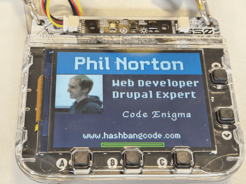
The end result is a screen that contains my name and some top line information about me.
Battery Level Indicator
In addition to my own information on the main display I wanted to add a battery indicator so that I could tell how much power was left on the badge. The badge object that is available as part of the system comes with a few functions that allow you to find out what sort of state the battery is in. For example, you can use the battery.battery_level() function to get the current charge of the battery as a percentage. The battery.is_charging() shows if the battery is receiving charge.
The following code will pick up the current status of the battery and draw a little graphic that shows a representation of that status.
def draw_battery():
    if badge.is_charging():
        battery_level = (badge.ticks / 20) % 100
    else:
        battery_level = badge.battery_level()

    if battery_level >= 80:
        battery_colour = battery_colour_high
    elif battery_level < 80 and battery_level >= 30:
        battery_colour = battery_colour_med
    else:
        battery_colour = battery_colour_low

    battery_width = 64
    pos = ((screen.width / 2) - battery_width/2, 115)
    size = (battery_width, 5)
    screen.pen = battery_colour_high
    screen.shape(shape.rectangle(*pos, *size))
    screen.pen = background_colour
    screen.shape(shape.rectangle(pos[0] + 1, pos[1] + 1, size[0] - 2, size[1] - 2))
    width = ((size[0] - 4) / 100) * battery_level
    screen.pen = battery_colour
    screen.shape(shape.rectangle(pos[0] + 2, pos[1] + 2, width, size[1] - 4))
The battery level is drawn in a very specific place on the who am I screen. The graphic doesn't resemble a battery, it's just a green bar across the lower part of the screen, but the internal colour changes depending on what level the battery is at.
QR Codes
The original badge application that comes with the option to show some social media links, but people have to copy down those details and that seemed like a shortfall. I wanted to rectify this by having a set of QR codes that people could easily scan links relevant to them.
Pressing the button to go to page 3 will display a QR code image and a small bit of text to show what the code linked to. I thought it was important to label the code since it's quite difficult to see what it is from just the code.
The up and down buttons could then be pressed to display a number of different images, each with a description.
The QR code images are displayed using the screen.blit() function along with the rect() function, which is used to draw the image in a set size and position on the screen.
Also, in order to allow the QR codes to be scanned well, the brightness of the screen it set to full using the built in function set_brightness().
qr_text = ''

# Ensure the screen brightness is at full so the codes can be scanned.
set_brightness(1.0)

if badge.pressed(BUTTON_UP):
    qr_current_image = qr_current_image - 1
elif badge.pressed(BUTTON_DOWN):
    qr_current_image = qr_current_image + 1

# Clamp value.
if qr_current_image < 0:
    qr_current_image = 0
if qr_current_image >= 6:
    qr_current_image = 6

if qr_current_image == 2:
    qr_image = image.load("assets/qr_linkedin.png")
    qr_text = 'LinkedIn'
elif qr_current_image == 3:
    qr_image = image.load("assets/qr_add_item.png")
    qr_text = 'Add Item'
elif qr_current_image == 4:
    qr_image = image.load("assets/qr_codeenigma.png")
    qr_text = 'Code Enigma'
elif qr_current_image == 5:
    qr_image = image.load("assets/qr_phil_mastodon.png")
    qr_text = 'Phil Mastodon'
elif qr_current_image == 6:
    qr_image = image.load("assets/qr_hash_mastodon.png")
    qr_text = '#! code Mastodon'
else:
    qr_image = image.load("assets/qr_hashbangcode.png")
    qr_text = '#! code'

screen.blit(qr_image, rect(30, 15, 100, 100))

screen.pen = color.white
screen.font = rom_font.ark
screen.text(qr_text, 1, 1, 0.5)
All the QR codes stored on the badge are created using the QR code generator tool on this site, which generates QR codes as images that can be downloaded. The badge can be a little picky over what images it can show (due to the constraints of the system mainly) I also reduced them to 8 bit monochrome images.
That's the MVP I wanted to add to the badge in place, so let's look at adding more functionality.
The Sensor Attachment
On the back of the Tufty2350 badge is an I2C connector, which means that we can connect Qwiic/STEMMA QT breakouts using a JST-SH to JST-SH cable. I bought the multi-sensor stick from Pimoroni a while ago, so I was able to attach this to the badge and make use of the sensor as part of the badge application.
Whilst we could just read from the sensor bar on every update of the badge I found that this overloaded the sensor and caused false readings. The best way of reading from the sensor bar is doing it every few "ticks" of the badge, which allows the sensor bar to be read correctly. This is a good example of using the built in badge.ticks property along with a last_ticks variable to see how many cycles have passed in the badge and act accordingly.
The following code will print the current time and then update the sensor readings every 1000 ticks of the badge.
screen.pen = color.white
screen.font = rom_font.nope

dt = datetime.now(timezone.utc)
time_text = f"{dt.year} {dt.month:02} {dt.day:02} {dt.hour:02}:{dt.minute:02}:{dt.second:02}"
screen.text(time_text, 10, 10)

try:
    if badge.ticks - last_ticks >= 1000:
        last_ticks = badge.ticks
        # Grab the latest sensor readings.
        sensorReadings()

    # Render the sensor readings.
    displaySensorReadings()
except:
    screen.pen = color.white
    screen.font = rom_font.nope
    screen.text("Sensor not found", 10, 25)
The sensorReadings() function takes the a sensor readings object and updates it with the latest values. These values can then be printed out in the displaySensorReadings() function, which just prints them out to screen in much the same way as the main page display.
def sensorReadings():
    global light_samples, sensor_readings

    screen.pen = background_colour
    screen.clear()

    # get the raw temperature values
    reading = temperature_sensor.read()

    # round the readings to 1 decimal place
    reading = [round(r, 1) for r in reading]

    # unpack the readings into sensible variables
    temp, pressure, humidity = reading

    # format the pressure reading
    pressure /= 100
    pressure = round(pressure)

    light_reading = light_sensor.get_reading()
    lux = 0
    if light_reading is not None:
        _, _, _, _, _, _, lux = light_reading

    sensor_readings.temperature = temp
    sensor_readings.pressure = pressure
    sensor_readings.humidity = humidity
    sensor_readings.lux = lux
This will render the sensor readings every cycle of the update function, and as the sensor readings are periodically updated they will be automatically re-printed with the new values quite quickly.
Pressing the middle button on the badge will swap to the sensor display, which worked very well. I have no way of correlating the pressure or luminosity, but the temperature has been the same as other thermometers in the house.
Connecting To WiFi
I wanted to do something interesting with the badge, rather than it just being a static business card with some QR codes. So I created something that people could interact with.
The first step was to create a small badge update form on this site that allowed users to enter short bits of text. These were stored in the Drupal CMS and could be retrieved using a simple REST resource.
The code on the badge was then added to connect to the site using the badge's built in WiFi adaptor. If the connection was successful then we run the code that pulls the items from the REST resource and saves them to a worditems object so that they can be rendered in the renderWordItems() function.
renderWordItems(worditems, words_offset)

if badge.ticks - last_ticks >= 6000:
    # Load the data from the network.
    last_ticks = badge.ticks

    if wifi.connect():
        getWordItemsFromRemote(worditems)
    else:
        wifi.tick()
        screen.clear()
        screen.text(f"Connecting to {secrets.WIFI_SSID}...", 10, 10)
Every 6000 ticks of the badge (about 6 seconds) the badge connects to the WiFi and grabs the REST data. The connection to the WiFi is handled by code in the badge operating system, so once a connection is made we can re-use it again.
Rather than finding some free WiFi and programming the badge to connect to that I created a mobile WiFi hotspot on my phone. That way I could pull data from the internet without having to configure the badge, making it easy to connect. What's good is that all of the network code is abstracted away from the user with a wifi class, which means I didn't have to start from scratch and write my own WiFi adaptor. A really neat touch my Pimoroni to include that.
The code to grab information from the REST resource is pretty simple as the API responds with JSON data and Micro-Python has built in functions to deal with that sort of data stream. Once we have the data we can then clear the items in the worditems object and fill them again.
def getWordItemsFromRemote(worditems):
    # Display a green blob in the corner when making a request.
    screen.pen = color.lime
    circle = shape.circle(150, 110, 6)
    screen.shape(circle)

    try:
        # Get the data.
        r = requests.get("https://www.hashbangcode.com/badge/[REDACTED]")
        j = r.json()

        worditems.items.clear()

        for item in j:
            worditems.items.append(item)
        worditems.items.reverse()
This simple system worked really well. People were able to scan a QR code to get access to the form, and could then post messages to the badge. People had fun all weekend posting messages to the badge.
Of course, I didn't create this system without the ability to remove messages. There was an administration screen in the CMS that I could use to remove messages, or even purge them all at the same time. Thankfully, no one abused the system.
The Final Result
The badge is high quality and well put together. Adding code to it was really easy and it only took me a few minutes to start writing some MicroPython.
I think the end result turned out really well. Here are a couple of images of the assembled badge, running the custom code.
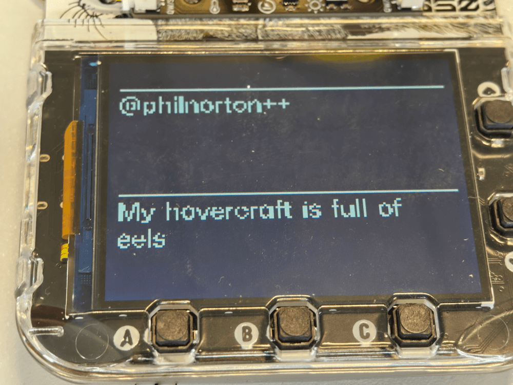
This is an image of the message board, where people could leave messages for me. I added a function to the up and down buttons to allow me to scroll through the messages, so I was able to receive more than just one message at a time.
The battery lasted pretty much the entire day of both conferences I took the badge to, which is impressive. I suggest also taking a battery backup with you as well as a battery top up comes in handy.
There is plenty of documentation on the Badgeware site, with examples of a few different badge applications. One word of warning is that whilst the docs site does go through every function available on the badge, they are a little lacking in some of the examples so it can be difficult to figure some things out. I had particular fun with the font as there are a number of different sections in the wiki that display font information, but each contains a piece of the larger picture on font rendering.
Do you have one of these badges? Have you managed to create your own application, or are you struggling with MicroPython? Please let me know in the comments.
If you're interested in giving this a go then you can pick up a Tufty2350 from the Pimoroni website. They have a speedy service and always get my orders correct, even when I add in some random cable or breakout board.
There are three variants of the Badeware system from Pimoroni. The one detailed here is the TFT display version, but also available is the Blinky (with a LED matrix display) and the Badger (with an E-Paper display). All powered by the same Raspberry Pi RP2350 chip.

Add new comment